![]()
Taming the
Cisco Nexus 9000
Part 6: Soldering
|
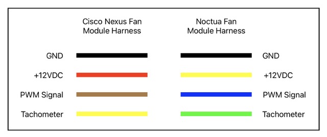
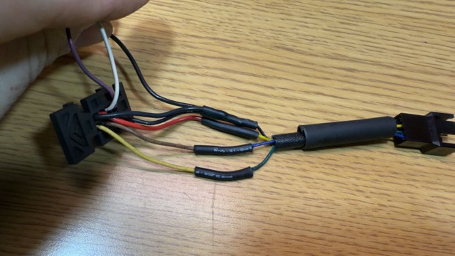
1. Observe the respective color codes of the Cisco and the Noctua fan harnesses:
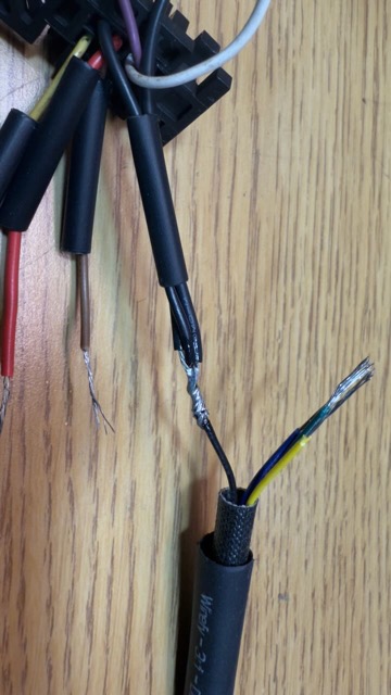
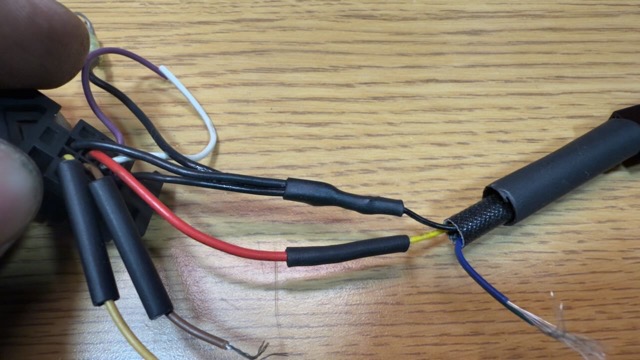
2. Join the three black GND wires from the Cisco self-aligning connector to the black GND wire from the Noctua pigtail, using an appropriate junction twist.
3. Heat-shrink the soldered black GND wire junction.
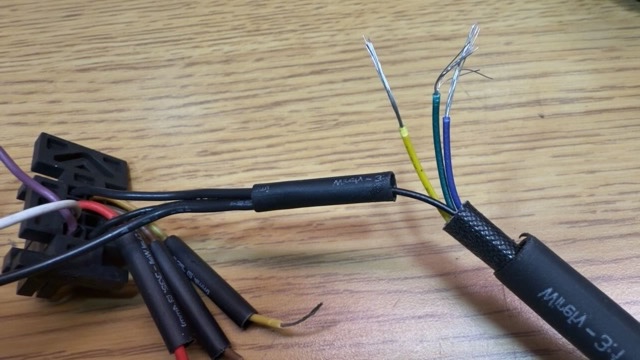
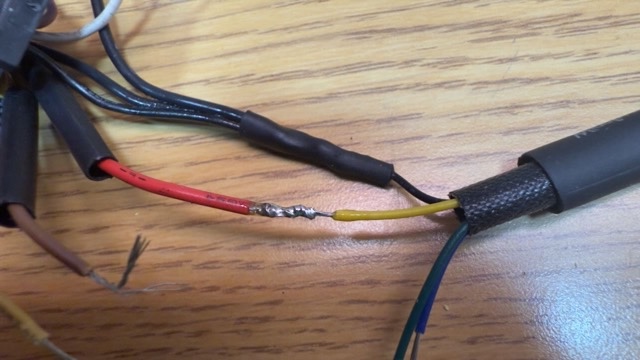
4. Twist, flux, and solder the red lead from the Cisco harness together with the yellow lead from the Noctua pigtail. Heat-shrink the junction.
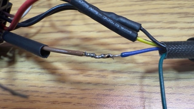
4. Twist, flux, and solder the brown lead from the Cisco harness together with the blue lead from the Noctua pigtail. Heat-shrink the junction.
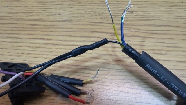
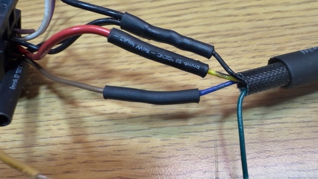
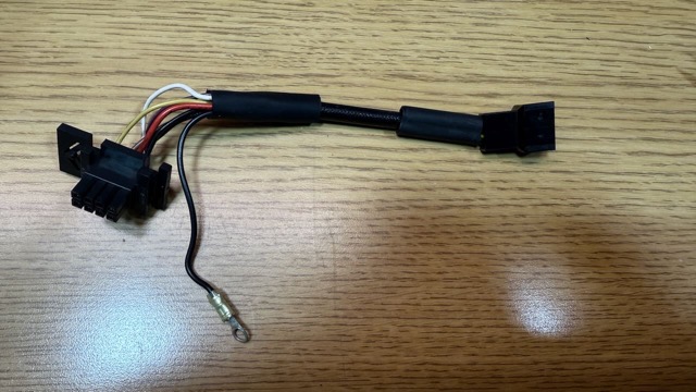
5. The Cisco harness is now correctly soldered to the Noctua pigtail, noting two black GND wires from the Cisco self-aligning plug and one black GND wire from the frame grounding terminal.
6. Slide one of the two pieces of heat-shrink tubing reserved from the Noctua pigtail over the combined junctions between the Cisco harness and the Noctua pigtail, making sure the Noctua jacket extends under the heat-shrink tubing. Tuck the cut ends of the unused purple and white wires into the heat-shrink tubing as well, to kepe them out of the way.
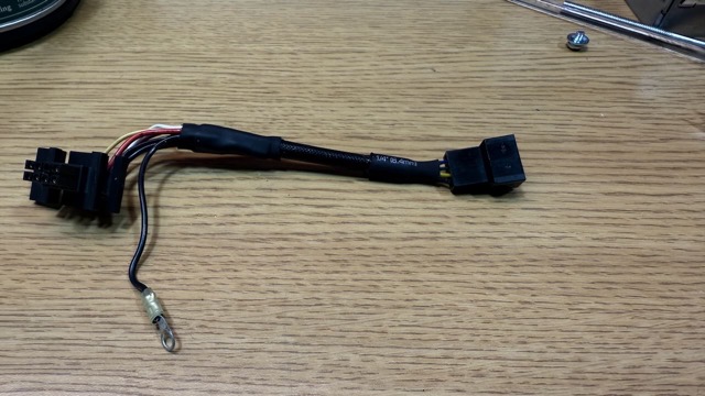
7. Sixth checkpoint: the modified harness is now complete.
Part 1 | Part 2 | Part 3 | Part 4 | Part 5 | Part 6 | Part 7 | Part 8 This information is supplied solely for educational purposes, and no claims are made as to its ownership or its fitness for any task. Commercial distribution or sale is strictly prohibited. All rights are retained by the original creators. |
|
|
Home FAQ The Files Full Text Search Site Updates
SheepShaver Unofficial Taming the Nexus 9000


Contents provided for educational purposes only.
Last modified Tuesday, 17-Jun-2025 04:23:35 UTC